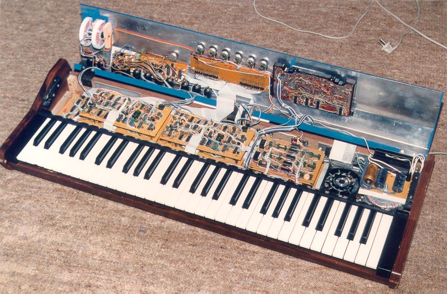
The MiMi-a opened
The MiMi-a is built entirely on copperless veroboard. The digital boards
are built with the components and wiring on the top of the board
and only the power
lines on the bottom side, whereas the analog boards have the components
one the top and most of the wiring on the bottom side, like conventional
circuit boards.
But since this is an analog synth, let's start with the analog boards.

With cover opened...
There are a number of circuit boards in the bottom of the case,
from left to right:
- The noise generator and cassette interface board. The noise is digitally
generated using a feedback shift register, with a period of about one
and a half minutes. It is used as an audio noise source, and also sampled
for use as a true noise input for the LFO S/H waveform.
- Voice boards 4-6 stacked on top of each other. Each voice board contains
the complete analog signal processing for one voice.
- Voice boards 1-3 stacked in a similar manner.
- The three ramp generator boards stacked on top of each other. Each
ramp generator board contains the analog portion of the three envelopes
and the LFO for two voices.
- Cooling fan. Strictly not necessary, it's quite cool (pun intended),
as the instrument physically comes alive with a bit of airflow and
vibration when turned on.
- The power supply unit, consisting of a toroidal transformer with
three secondary windings, in conjunction with a small transformer to
deliver -20V for the display. Also visable is the rectifier cooling fin and
the filter capacitors.
In the lid of the case the keypad is mounted, together with
decoding logic glued directly to the board. (Yes, if someone wants to know,
it's from a desk calculator.) Also, the display driver board under the
display, and just behind the output connectors, the output assigner
board for mapping the voices to the six individual outputs.
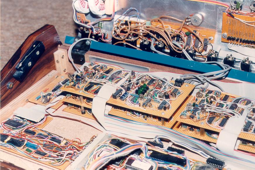
The voice boards are worth looking closer at, as they took about a day
each to build, after the initial design had been worked out on a breadboard.
6 continuous days of soldering (and not just 9-5 either), and I was, well,
tired, to put it mildly.
Evident on the voice board are the four capacitors in a row
in the filter section, surrounded by transistors, spilling the beans that
the filter is actually a Moog design to start with. The signal
processing is in a logical flow from left to right, with the oscillators'
analog section on the extreme left, continuing with the wave shapers
and ring modulator,
waveform selector and modulation routing analog switches (partly hidden by the ribbon cable),
oscillator mixer and filter-by-oscillator-B VCA's, filter, and finally the VCA on the right.

Close-up of a MiMi-a voice board stack
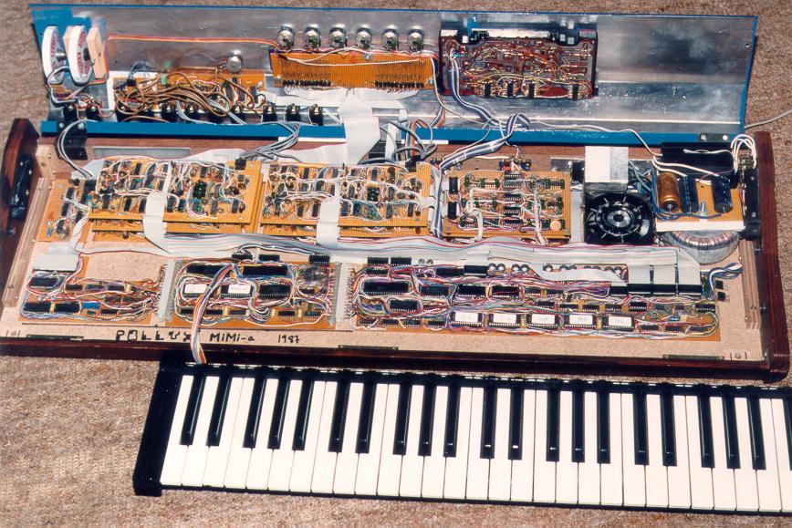
But what about the digital electronics? Well, remove the keyboard, and,
voila...

...and keyboard removed
From left to right, the boards are:
- The Display Driver board, with a custom-built driver for the
32-character-by-14-segment vacuum flourescent display. (Ok, let's face it,
I had no idea where to get a proper driver chip).
- The CPU board, with the Z80 CPU, keyboard and keypad interfaces, MIDI UART
and drivers, ROM, RAM and battery backup circuit.
- The D/A board, which contains the 12-bit CV D/A converter, hardware
multiplier consisting of 5 27128 EPROMs and 3 4-bit adders, oscillators'
digital section (comprised of 6 74LS124 dual high-frequency VCO's and
4 8253 triple 16-bit timers), and envelope generator digital section
(current value and parameter memories), as well as miscelaneous digital
logic, such as the timer interrupt generator.
From initial design to finalization of the first version, it took about half a
year. That includes design, breadboarding, soldering, hardware and
software. At that time, the output assigner was not completed, and a number
of software modules were not finished, like the VGC and split/layer modes.
The software now comprises about 14 Kbytes of code for the main operating system,
with a few additional kilobytes for the cassette storage and diagnostic modes,
and further kilobytes for frequency (oscillator and filter tracking)
tables. Two 27128 chips are used for program storage.
A few updates on the analog boards have also been done after the
original design, including the linear/exponential VCA, but no major
design changes have been effected.
Back to the MiMi-a page.


