Butoba clockwork tape recorders
Wound-up machines?
In the 1950's, small speed-regulated DC motors were unusual, and so it was
natural for a company that specialized in the manufacture of clocks
and precision mechanics to start using clockwork motors for
driving tape recorders. The motor used is principally
identical to the type found in old record-players, however, there are a
couple of differences. First of all, speed accuracy is much more important,
as there is no audible means of checking the speed during record. Secondly,
tapes play for much longer than the 3 or 5 minutes required to play a 78 rpm
record. And finally, because of the lack of a turntable, there is no
intrinsically large mass to filter out speed variations.
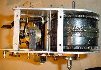
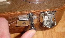
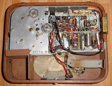
Two views of a Butoba spring drive unit. In the left picture, one of
the two large mainspring canisters can be seen.
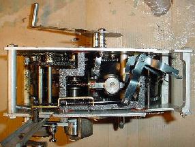
In the right picture, the governor assembly is visible (with one
of the three round weights mounted on its leaf spring facing directly into the
camera).
Looking from another point of view, comparing the Butoba drive unit to the now
conventional method of using an electric motor and flywheel to drive the tape,
the Butoba motor stands out on a couple of points, apart from the spring drive:
-
First of all, the drive mechanism uses gears for the transfer of energy.
Normally gears are a no-no for drive units intended for audio use.
In the Butoba,
the cogs of most wheels except the mainsprings are slanted, which results in
an even transfer of movement. Several of the larger cogwheels are made of a
fibre material instead of metal, which further damps vibrations. Finally,
liberal application of graphite grease brings vibrations to a minimum.
Still, one can't help wonder how much wow and flutter is caused by
using gears instead of a friction drive. At any rate, proper lubrication
and alignment of parts is crucial to obtaining a flutter-free
tape motion.
-
Secondly, there is no flywheel, at least not in the conventional sense, mounted
on the capstan. There is a fast-running governor mechanism, which has
rotating weights, controlling the speed, and this assembly may be considered
a flywheel of sorts.
-
Finally, the capstan diameter is large, in the order of 2 cm. Normally
large capstans are to be avoided because of the difficulty in manufacturing
such a large rotating component with the precision required in a machine
for playing audio.
All in all, the drive mechanism cannot have been cheap to manufacture, with
lots of machined parts, especially considering the precision needed
to minimize speed fluctuations. Not only the drive mechanism, but
parts like the reel tables are machined and not stamped or moulded.
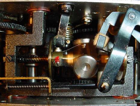
The governor in operation: weights extended by centrifugal force,
their rotating motion frozen by the camera flash
As a final note on the drive unit, it can be noted that not everything is
driven by cogwheels, the exception being the take up reel clutch which
is actually driven using a rubber belt.
Winding up
|
The crank for the motor is located on the underside of the machine, with
the speed selector being located here as well. About 70 or 80 turns
will wind up the springs completely.
|
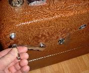
Rewinding - and a sore thumb
|
The clockwork motor is only used for normal forward drive. There is no fast
forward on these machines, and rewind is accomplished manually, by
pressing a rewind button repeatedly, which via gears turns the supply
reel. Unfortunately, during ordinary play, the rewind gears on the supply reel
tend to rattle audibly, especially at the end of a reel at the higher speed.
|
|
Pushbutton control
|
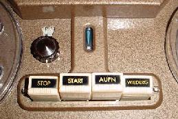
A Butoba hallmark is push-button operation. Although the rewind button
cannot really be considered a push button in the ordinary sense, standard
push buttons are used to control all other
tape operations; two buttons being used for start and stop, and two other
buttons being used for record/play selection. There is no record interlock;
pressing record and then start immediately starts a recording.
The brown knob in the picture on the left is the reset knob for
the running-time counter; the counter itself is visible in the little
window above the knob. It was not present on the earliest models.
The slot in the middle is the opening for the DM71 indicator tube.
|
Amplifier control panel
|
The amplifier controls and input/outputs are concentrated on a small
recessed panel on the side of the machine. There are no markings on
the panel. The left knob is the tone control, whereas the right knob
controls the volume. Both knobs are active also when recording.
The three connectors on the panel are a type of thin jack connector
that I've never seen anywhere else.
From left to right they are line output, line input and microphone input.
Early models had only this panel; on later models, as can be seen in
the picture, an unusual male DIN connector is used for an external
power supply connection. (I don't know what 'BNZ' stands for, but it
sure sounds German). Later machines like the TS6 also have a couple
of banana plug connectors for connecting headphones.
|

|
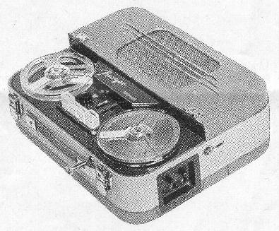
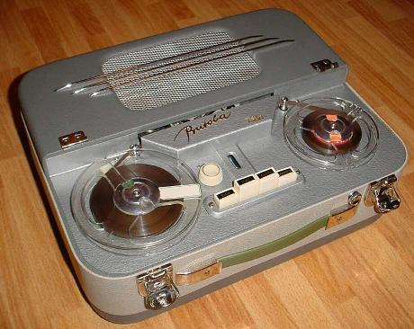
The "Export"
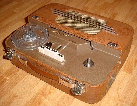
The Butoba "Export"
The "Export" is an example of a typical Butoba spring-drive tape
recorder with an all-tube amplifier. Not the first type to be
produced (earlier models lack the running-time counter and external
power supply input), I would guess it is from around 1955.
Rear view with cover opened; drive unit on the left,
amplifier unit on the right. The speaker below is
covered in white cloth!
|
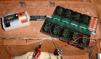
The amplifier uses 'battery tubes', i.e. with a filament voltage of 1.4V,
and an anode (B+) voltage of 90 or 100V. When the recorder was built,
such batteries were readily available for use in portable radios.
Operating the machine today can be slightly problematic, as it's difficult
to find a battery that delivers anything over 9V. However, current
drain is low, and connecting ten standard 9V batteries in series results
in 90 volts, and yields several hours of playing time. A standard
"D" cell can be used for the filament battery. Interestingly, 9V batteries
are mechanically very easy to connect in series as can be seen
in the picture to the right.
|
Using modern day batteries
|
15 Minutes
Simple as the mechanics are, the machine boasts two speeds, 7 1/2 and
3 3/4. At the higher speed a running time (per wind-up) of 15 minutes
can be obtained, and a running-time-counter (the knob above the row of
push buttons) is used to keep track of this. At the lower speed,
twice that time can be achieved. However, speed regulation
at this speed is not too good, the machine running a couple of per cent
too fast just after wind-up, and slowing to a couple of per cent below
rated speed when the running time has elapsed.
The main reason for the lack of speed regulation at the lower speed
is that the governor is turning quite slowly at this speed,
meaning that the weights
are not extended very far on their springs, making the whole mechanism
sensitive to friction and the amount of energy available from the mainsprings,
which varies during the playing time.
Technical data
Not too exhaustive this, as I have no data sheet for the machine.
The frequency response has been determined by measurement.
- Date of manufacture: Probably around 1955
- Maximum reel size: 5" (13cm)
- Number of tracks: 2 (half track), mono
- Speeds: 7 1/2 ips, 3 3/4 ips (19 cm/s, 9.5 cm/s)
- Frequency response: 100-13000 Hz at 7 1/2 ips, 100-5000 Hz at 9.5 ips.
- Bias frequency: 35 kHz
- Tube complement: DAF91 x2, DL94 x3, DM71
- Motor: Spring drive with two mainsprings
- Running time (per wind-up): 15 minutes at 7 1/2 ips (double at half speed)
- Speed regulation: centrifugal governor
- Power supply: 1.22V NiCd accumulator for filaments,
90 or 100V dry battery for B+
- Power consumption: Filament: 400 mA, B+: 20 mA
The TS61
The Butoba TS61
The TS61 was probably Butoba's last clockwork recorder. Externally, it looks
virtually identical to the "Export" above. Internally, however, the
chassis has been redesigned, and the machine uses transistors instead of
tubes. In fact, apart from the output and driver transformers, the
electronics are the same as in the later
MT4 and
MT5. The machine shown is from 1959, which
is probably when the model was introduced.
Transistorized design
Still retaining the DM71 indicator tube for the record level, the TS61 uses
an all-transistor design for the electronics, powered by four "D" cells.
These should last a long time, as the current drain at low playback volumes
is a mere 30mA. Most likely, this was the main reason to retain a clockwork
machine in the range, i.e. the long playing time compared to a motorized
design.
Slight redesign
Heavier governor weights, requiring slower speed to maintain regulation,
a smaller capstan diameter, and most likely changes to the mainsprings as well,
give this recorder a playing time (per wind-up) of 22 minutes or more, and
the higher speed which is 3 3/4. At the lower speed of 1 7/8, 40 minutes
can be obtained.
Compared to the "Export", the chassis has also been redesigned; this however
turns out to be a bit of mixed blessing. While it is now possible to
remove the drive unit without removing the whole chassis from the case,
this must be done in order to replace the clutch drive belt, which on the
"Export" is simply a matter of removing the upper capstan bearing.
An interesting side note is that the machine, like earlier models, was offered
in several color schemes. Apart from the sombre two-tone grey vinyl depicted
above, green or red crocodile could be chosen.
Technical data
- Date of manufacture: 1959
- Maximum reel size: 5" (13cm)
- Number of tracks: 2 (half track), mono
- Speeds: 3 3/4 ips, 1 7/8 ips (9.5 cm/s, 4.75 cm/s)
- Frequency response: Quoted as 50-9000 Hz at 3 3/4 ips, however, I
believe this is valid for the older TS6, the TS61 having the same upper
range as the MT5, i.e. around 13000 Hz.
- Bias frequency: 35 kHz
- Transistors and tubes: OC603, OC75, OC71, OC76, OC74 (x2), DM71
- Motor: Special spring drive with two mainsprings.
- Running time (per wind-up): 22 minutes at 3 3/4 ips (double at half speed)
- Speed regulation: centrifugal governor
- Power supply: 4 "D" cells (R20)
- Power consumption: playback: 30 mA, recording: 170 mA
User and Service Manuals
The user manual for the TS61 is, as for most equipment of that era,
short, just a folded sheet of paper. It's available here as a two-page PDF file.
If you want an authentic replica, make a double-sided printout, and fold
in thirds along the two lines.
There's also a brochure available, again rather short, just a single fold
this time, so four pages in total.
The service manual for the TS6 is available below, in German language.
(The TS6 is essentially identical to the TS61, except that the electronics
is built on tag boards rather than PCB's.)
It includes descriptions, repair instructions, lubrication chart,
spare parts list, schematics and numerous pictures.
This page © Copyright 2003-2014 Ricard Wanderlöf
Back to my Butoba page.